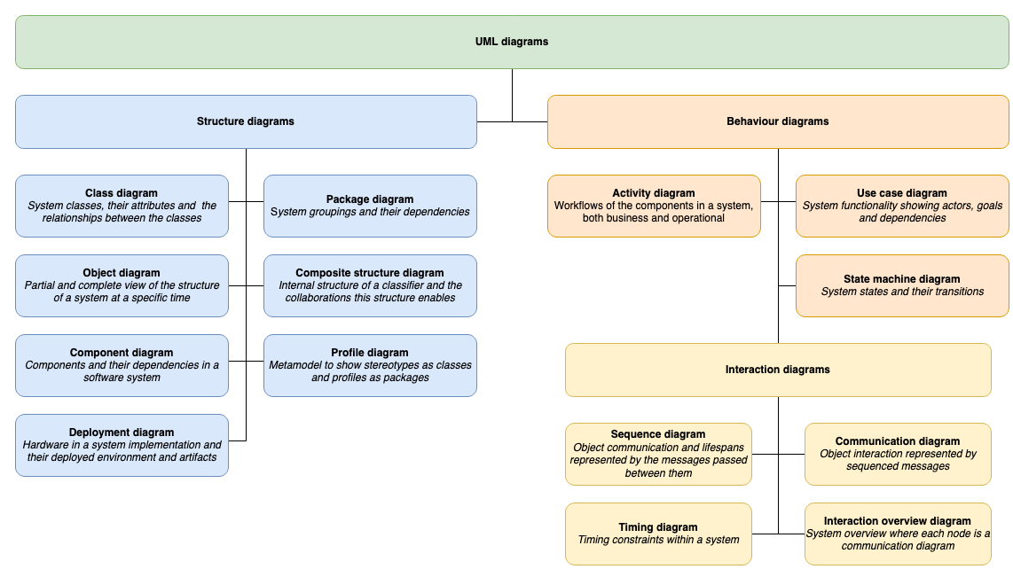
Create UML class diagrams
UML class diagrams are used to illustrate the structure of a computer program. They detail the types of data or attributes stored within each ‘class’, the methods (operations or functions) that each class provides, and the relationships between the classes.
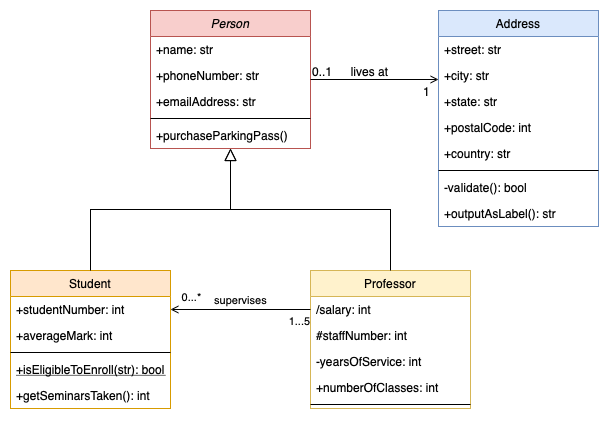
Class diagrams are likely the most common and important type of UML diagram.
While they commonly document an existing application, you may find your team creates cleaner code when you draw a class diagram before any implementation starts.
Do UML class diagrams need to be detailed?
Accurate and detailed class diagrams are important when changing an existing application, or re-implementing it in another programming language. Specification and implementation details are useful when multiple teams work on the same program.
You can create rough class diagrams using just the names of the classes and drawing their relationships. Use this conceptual level of detail to get feedback on ideas.
While UML has a well-defined notation, you can ‘relax the rules’ in rough class diagrams.
On this page
Draw UML class diagrams in diagrams.net
The shapes you need to create class diagrams are in the two UML shape libraries.
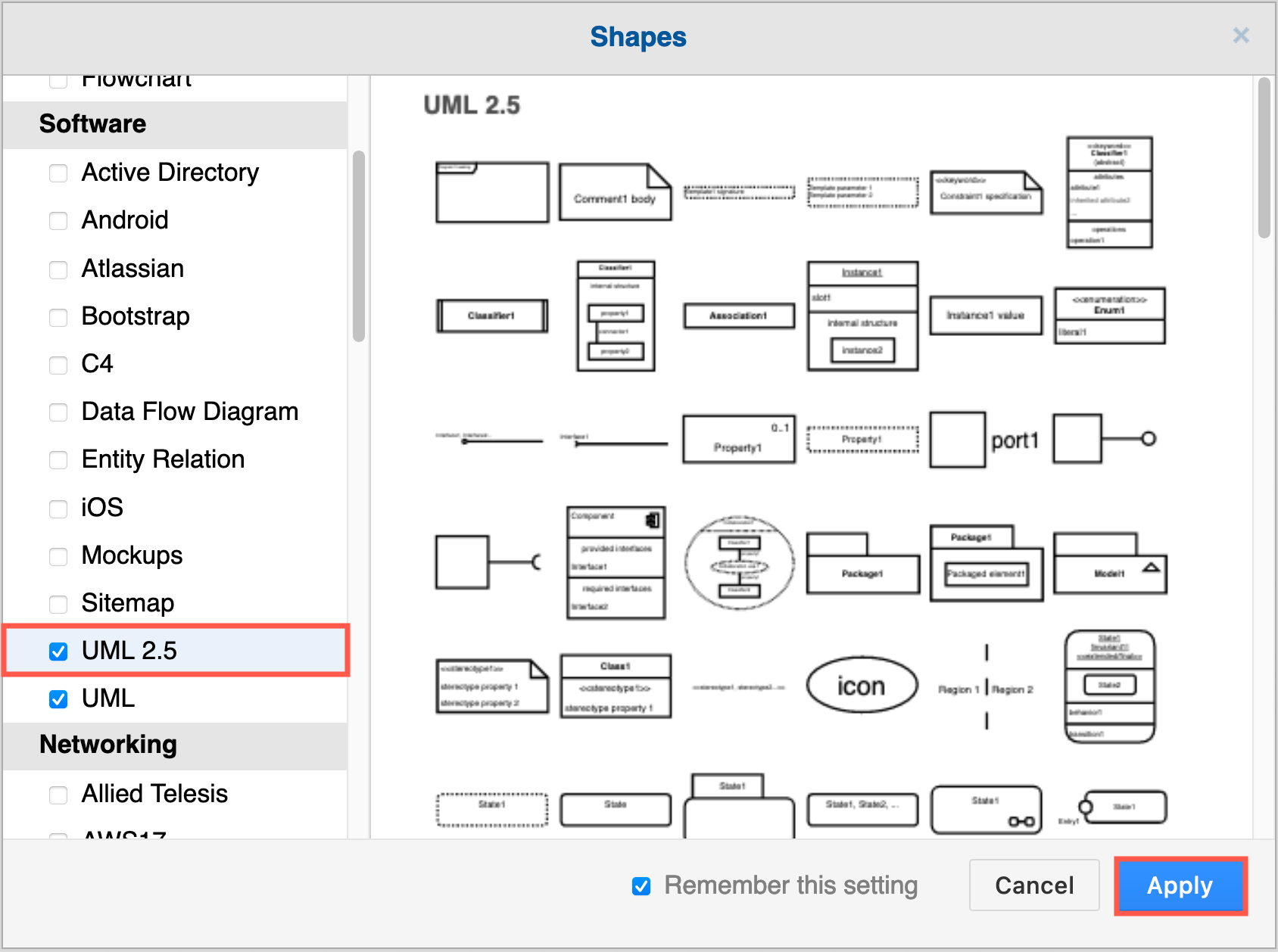
Enable the UML shape libraries
- Click on More Shapes at the bottom of the left panel.
- Enable the UML 2.5 and UML shape libraries in the Software section.
- Click Apply to return to the diagram editor.
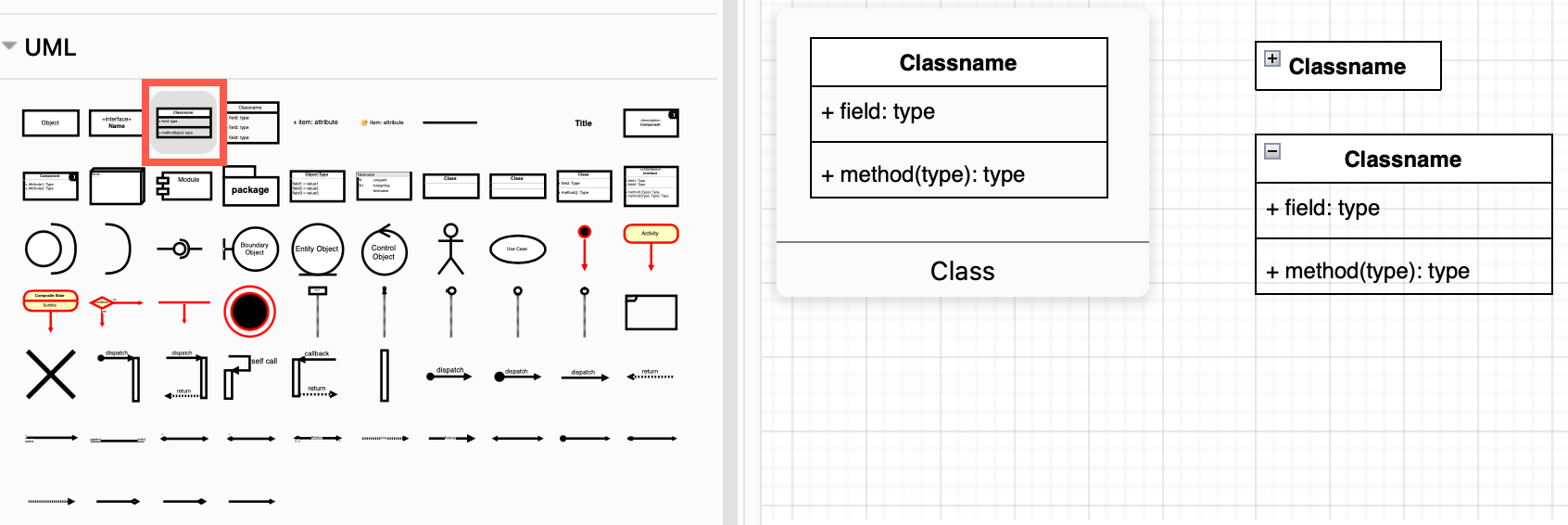
Most class shapes are in the main UML shape library. Hover over any shape in the shape library to see a larger preview.
Tip: The first two class shapes in the UML shape library are collapsible, making it easy to simplify a complex diagram without recreating it from scratch.
Use a template or example class diagram
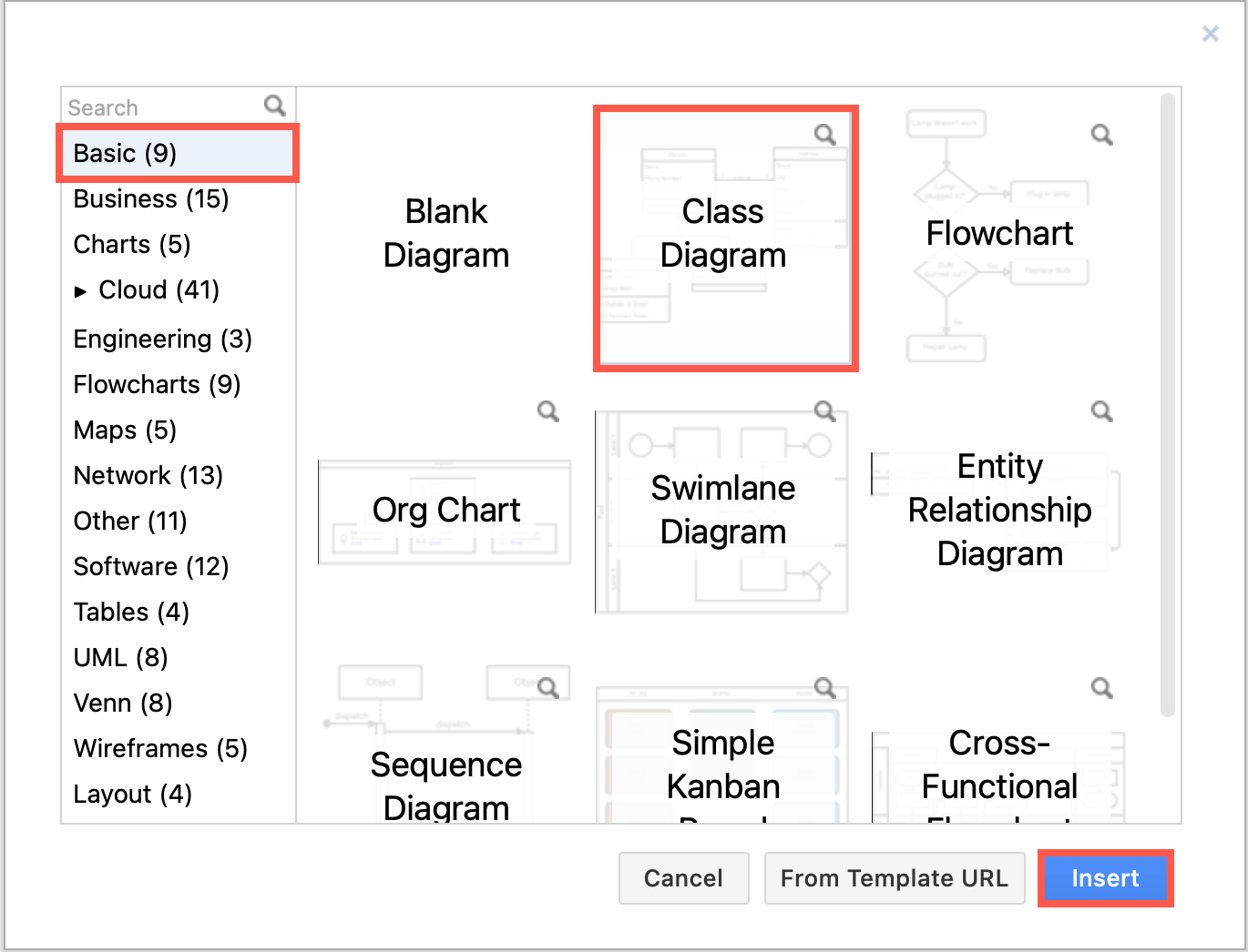
- Start a new diagram, or click Arrange > Insert > Template to open the template manager.
- There is a simple example in the Basic or Default template category.
Click on the magnifying glass to see a larger preview.- Software category: complex class diagrams.
- UML category: higher level class diagrams, and package diagrams.
- Select a template, and click Create or Insert.
Work with class shapes
UML class shapes always have a Class Name.
Classes in detailed diagrams have two additional sections for attributes and methods, and usually follow the UML notation, detailed in the sections below.
Detailed UML classes are separated into three sections with the class name at the top.
- The middle section contains the attributes (data or variables) of the class:
attributeName: type - The lower section contains the methods (operations or functions) that the class can execute:
methodName(parameterName: type): type
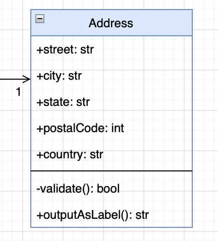
Parameter names, and data types are optional. They are typically used in a detailed class diagrams of an implementation or for formal specification documents.
Click on a class shape on the left in diagrams.net, or drag one onto the drawing canvas. The UML 2.5 shape library contains some specialised class shapes.
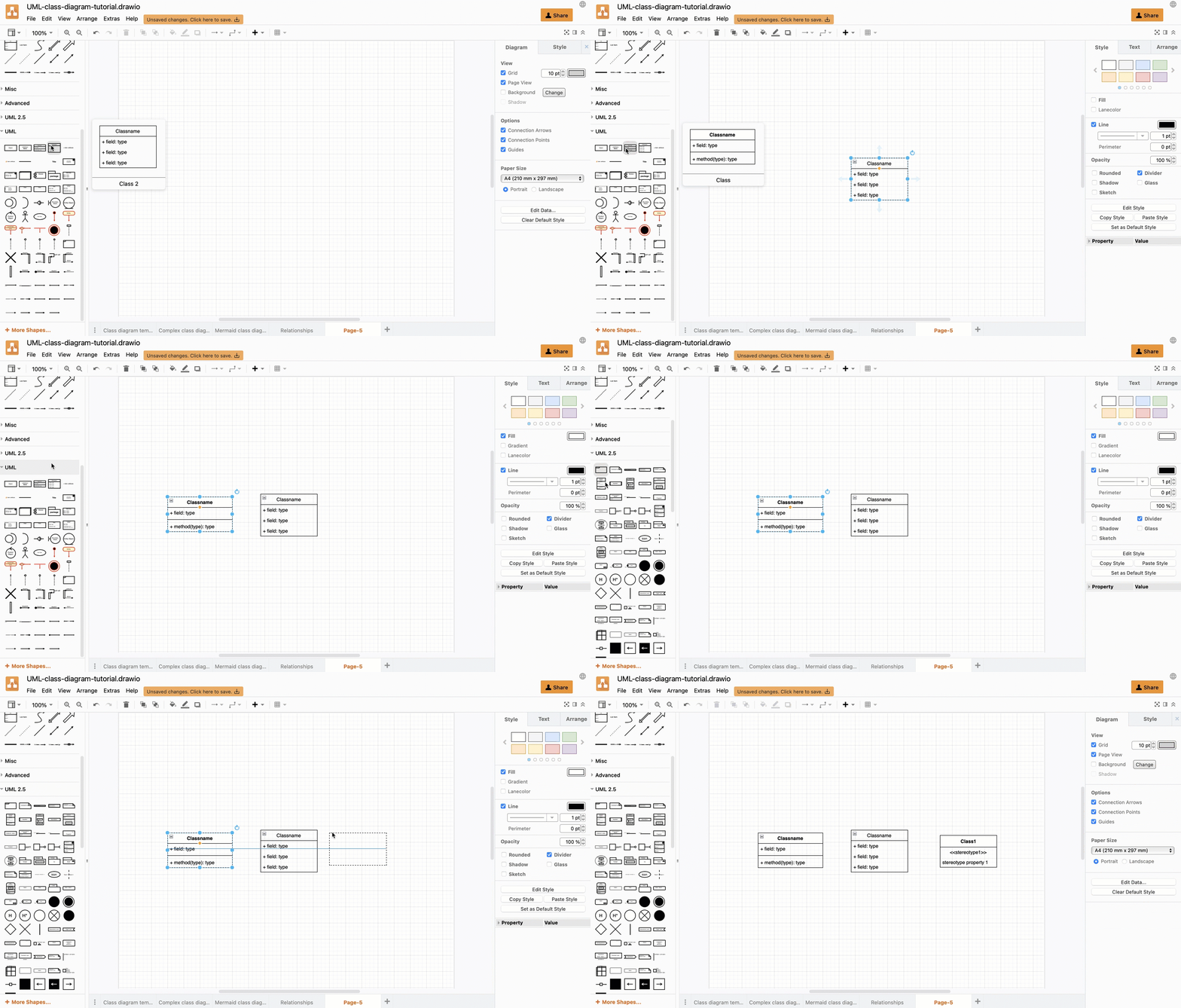
Tip: Work with class shapes as you would other table shapes including entity shapes in ER diagrams.
Editing UML classes in diagrams.net
Select a row inside a class shape: Click on a class shape once to select the entire shape. Click a second time, this time on a row inside the class, to select that attribute or method row.
Rename a class: Select the class and start typing to change its name.
Edit an attribute or method: Double click on the attribute or method to highlight all of the text. Start typing to replace it, or use the cursor keys or mouse to reposition the cursor within the text.
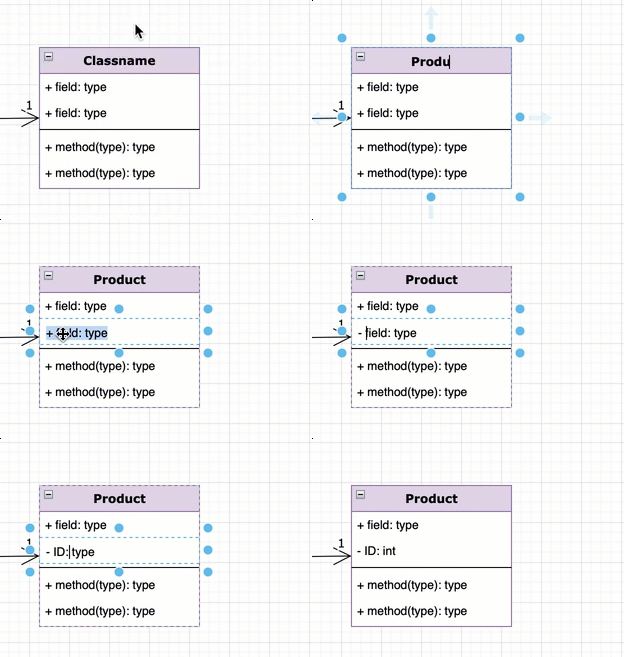
Add an attribute or method: There are many ways to add new rows to class shapes in diagrams.net.
- Add an attribute or divider from the library: Drag an
Item 1(attribute) orDividershape from the UML shape library and drop it on an existing class shape on the drawing canvas in the position where you want to insert it. - Clone a row: Select a row, and press the keyboard shortcut
Ctrl+Enteron Windows orCmd+Enteron macOS to insert a clone of the selected row immediately below. TheCtrl+D/Cmd+Dkeyboard shortcut or right-clicking on the row and selecting Duplicate from the context menu work in the same way. - Add a blank row: In the Arrange tab of the format panel, click the Insert Row After or the Insert Row Above button. If you had selected the entire class shape, a blank row will be inserted at the end or at the start of your class, otherwise it will be inserted before or after the selected row.
- Move an attribute or method from another class: Drag a row from one existing class and drop it on another.
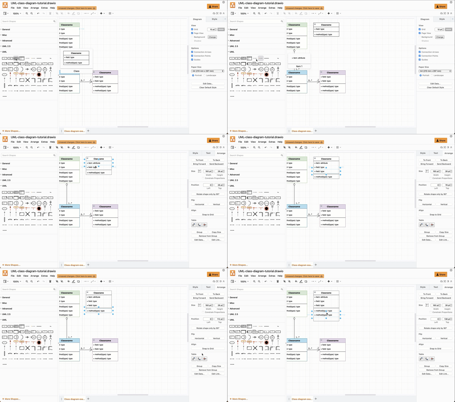
Delete a row: Select the row, then press Delete or right-click and select Delete from the context menu.
Tip: To reposition rows inside the class shapes, simply drag them to a new position.
Using UML notation in class diagrams
UML diagrams often follow a strict notation so that they can be easily turned into (or generated automatically from) code.
Of course, these ‘rules’ can be relaxed, as the basic class diagram template in diagrams.net shows. Even so, it is best to use a consistent naming style.
Attribute and method names in UML notation
Class names are usually in bold. Abstract class names are often written in italic.
Attribute and method names are typically written in lowercase, or camel case (forExample). Abstract methods are usually written in italic.
Visibility
The visibility of attributes or methods is indicated with a symbol before their names.
+Public elements are accessible from outside that class.-Private elements are only accessible to methods inside that class.#Protected elements are only accessible within its namespace (a group of classes and packages).~Package elements are only accessible within its package namespace (a group of related classes). Package diagrams are a specialised form of class diagram.
A forward slash / indicates an attribute is derived or computed from other attributes.
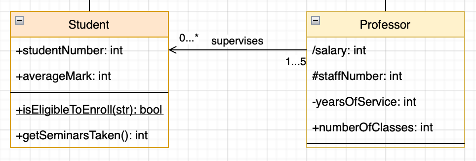
Scope
- Instance scope is assumed by default - attributes can have different values whenever that class is instanced, and the methods that are executed may alter that instance.
- Class scope or static scope is shown by underlining the name of an attribute - attribute values are the same across all instances of that class.
Type
You can add the data types to attributes and methods, including both the data passed to that method, and the data returned by it. Use a colon followed by the data type. For example: +name: string or +area(radius:float) :double
Connectors for relationships in UML class diagrams
Define the type of relationship between classes using a connector that has a specific symbol, labels at either end, and either a solid or dashed line.
- Inheritance (generalisation): An open triangle at the parent class. This shows that the subclasses are specialisations of the parent class - they extend the parent class.
- Implementation (realisation or execution): A dashed line with an open triangle at the blueprint class. This is used where a class implements the functionality of a ‘blueprint’ class, and may be implemented differently depending on each class that implements it.
- Dependency: A dashed line with an open arrow. If the definition of class 2 changes, it will change class 1, but not the other way around (depends on).
- Association: A solid line between two classes. Add arrows at either end or both ends to show that the classes are aware (or unaware) of each other.
- Aggregation: An open diamond at class 1. A special type of association that shows that class 2 is a part of class 1.
- Composition: A solid diamond at class 1. A special type of aggregation that shows that class 2 can not exist without class 1.
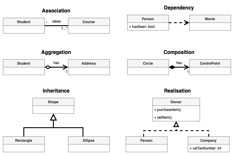
Open these relationships in diagrams.net
Tip: When two classes are aware of each other, and may use each other’s attributes or methods, place an association with arrows at both ends to indicate a bidirectional association.
Draw class relationships in diagrams.net
Click on or drag the connector you want to use from the UML shape library, then drag each end and drop it onto a class shape on the drawing canvas.
Alternatively, draw a connector from class 1 to class 2 or select an existing connector. Then change its source and target ‘arrows’ from the drop down list in the Style tab of the format panel.
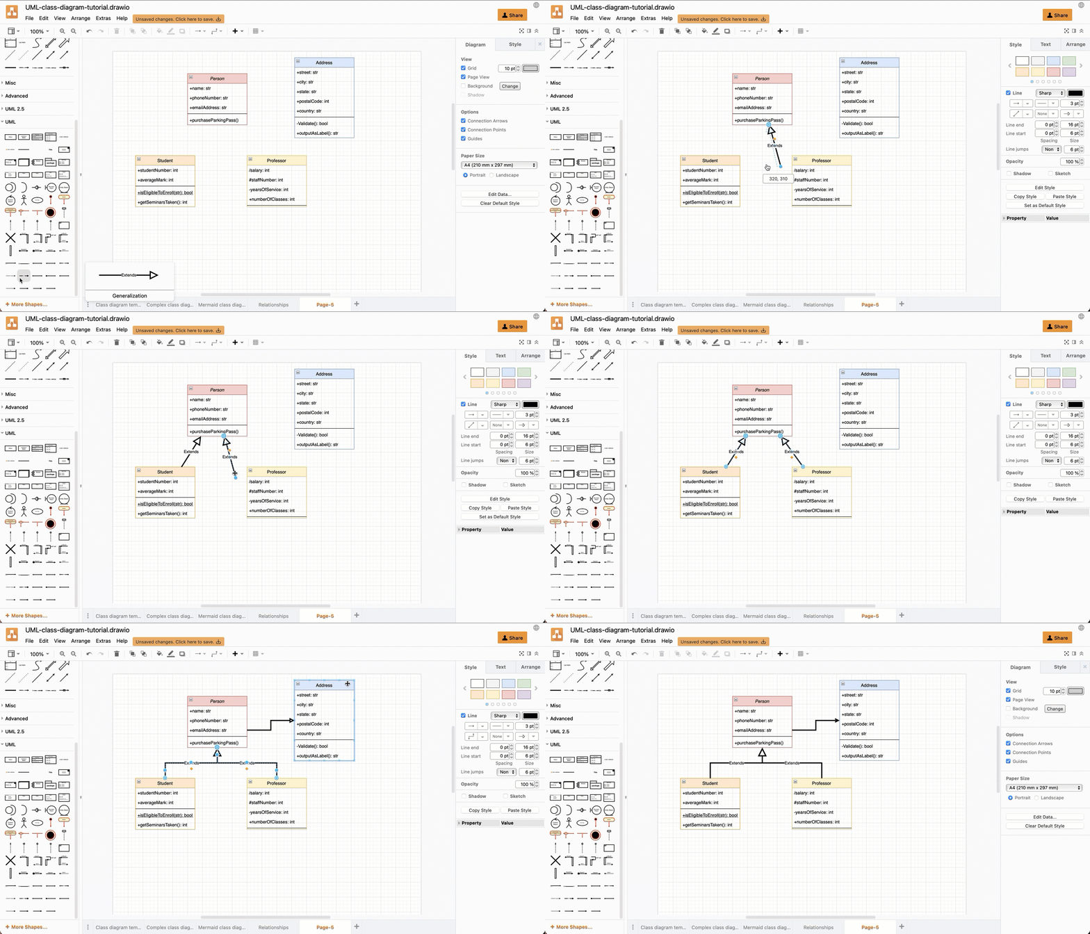
Tip: Drop a connector end on the class name while the outer edge of the class is highlighted in blue - the connector will float around the class as you move it on the drawing canvas.
Learn more about working with connectors in diagrams.net
Connector labels
You can add labels to a connector to further define the relationship between the classes.
- Specify how many instances of each class are in the relationship: one to one, one to many, many to many, an exact number, etc.
- Explain why the relationship exists.
- Note ownership or roles.
- Clarify visibility.
- …

Notes in complex UML class diagrams
Add a note shape and connect it to a class with a dashed or dotted arrow to include additional information. Use the Comment or Constraint shapes from the UML 2.5 shape library.
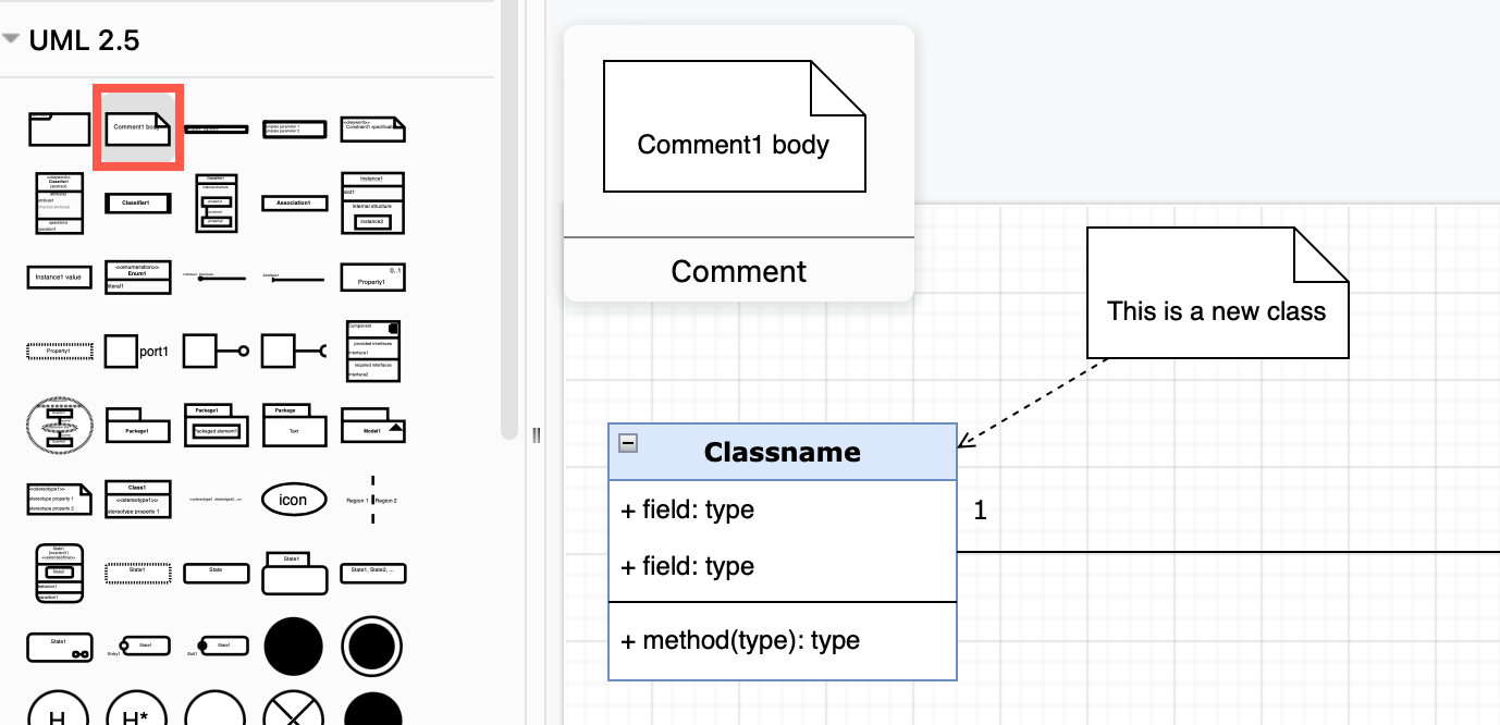
For more about UML notation, please refer to the UML 2.5 specification.
Related
To collaborate remotely on a rough class diagram with your colleagues, use the Sketch online whiteboard theme to minimise distraction. Share your cursor in real time with your team when you store the diagram file in Google Drive or Microsoft One Drive.
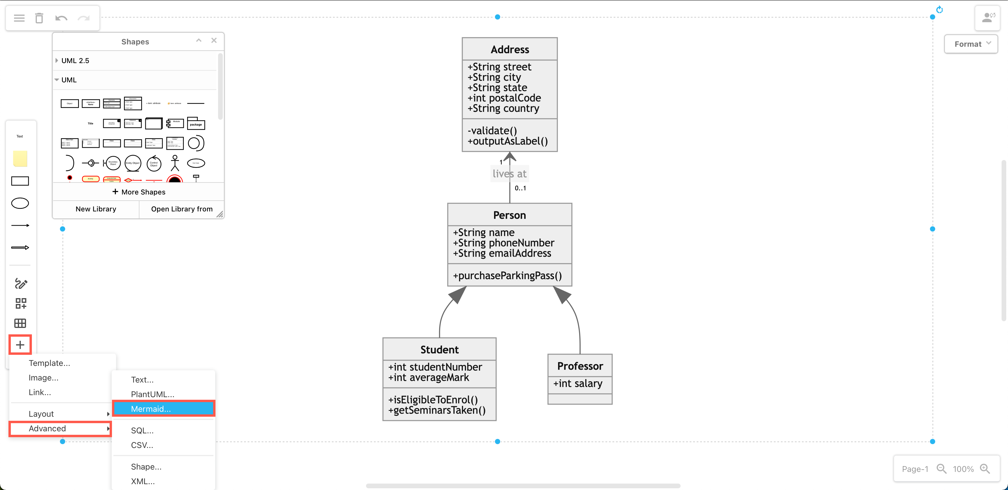
Describe classes and their relationships in Mermaid notation and generate a diagram automatically from the text. Select Arrange > Insert > Advanced > Mermaid from the menu.
Generate a PlantUML diagram in the same way: select Arrange > Insert > Advanced > PlantUML from the menu.
Note: If you are using the Sketch whiteboard theme, click + in the toolbar, then select Advanced to see the Mermaid and PlantUML options.
Other types of UML diagrams
The UML specification details notation for many different types of diagrams to model the behaviour and data of a system in many different ways.
Learn more about the following UML diagrams:
